Senin, 29 November 2010

Integrating ADC

An integrating ADC is a type of analog-to-digital-converter that converts an unknown input voltage into a digital representation through the use of an integrator. In its most basic implementation, the unknown input voltage is applied to the input of the integrator and allowed to ramp for a fixed time period (the run-up period). Then a known reference voltage of opposite polarity is applied to the integrator and is allowed to ramp until the integrator output returns to zero (the run-down period). The input voltage is computed as a function of the reference voltage, the constant run-up time period, and the measured run-down time period. The run-down time measurement is usually made in units of the converter's clock, so longer integration times allow for higher resolutions. Likewise, the speed of the converter can be improved by sacrificing resolution.
Converters of this type (or variations on the concept) are able to achieve high resolutions (8.5 digits, or 28 bits, in the case of the Agilent 3458A digital multimeter), but often do so at the expense of speed. The Agilent 3458A, for example, only achieves its highest resolution at a rate of six samples per second. For this reason, these converters are not found in audio or signal processing applications. Their use is typically limited to digital voltmeters and other instruments requiring highly accurate measurements.
Minggu, 28 November 2010

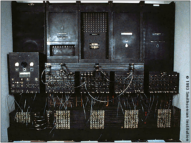
The First Electronic Computer: The ENIAC


In 1946, John Mauchly and John Presper Eckert developed the ENIAC I (Electrical Numerical Integrator and Calculator). The U.S. military sponsored their research; they needed a calculating device for writing artillery-firing tables (the settings used for different weapons under varied conditions for target accuracy). The Ballistics Research Laboratory heard about John Mauchly's research at the University of Pennsylvania's Moore School of Electrical Engineering. Mauchly had previously created several calculating machines, some with small electric motors inside. In 1942 he had begun designing a better calculating machine based on the work of John Atanasoff, which would use vacuum tubes to speed up calculations.

Selasa, 08 Juni 2010

Light Flasher

This is a very basic circuit for flashing one or more LEDS and also to alternately flash one or more LEDs.
It uses a 555 timer setup as an astable multivibrator with a variable frequency.
With the preset at its max. the flashing rate of the LED is about 1/2 a second. It can be increased by increasing the value of the capacitor from 10uF to a higher value. For example if it is increased to 22uF the flashing rate becomes 1 second.

There is also provision to convert it into an alternating flasher. You just have to connect a LED and a 330ohm as shown in Fig.2 to the points X and Y of Fig.1. Then both the LEDs flash alternately.

Rabu, 19 Mei 2010

Atmel AT89Sxxxx Series Min-Sys

INTRODUCTION

Now this is another kind of design but use a minimum system types using Atmel MCS51 S-series with ISP programming. So with this kind of board, the chip do not need to remove just programmed on board. Programed using ISP programming could be done directly through LPT parallel port. There are many programming software could be found on the internet. Some that I could find and much realiable eq.: AEC-ISP programmer, this kind is DOS version. Could be download at : AEC-Electronics. Also ISP programmer made by Asim Khan, could be download at : Asim Khan's ISP software, this kind is a windows version. Besides that there is software from Adam Dybkowsky which run both version of programmers. It could be found at : Adam's Home Page ISP PROG ATMEL89Sxx. Every programmers used its own ISP cable.

On Tauhid

Allah--ta`ala--has said: "I have not created jinn and
mankind except to serve Me . . . And to every people We sent a
prophet to convey to them that they ought to serve Allah and
avoid at-taghot. . . . Your Lord has decreed that you shall
serve none but Him, and show kindness to your parents . . .
Serve Allah and do not associate aught with Him . . . Come, let
me tell you what your Lord has forbidden you; namely, that you
do not associate aught with Him." (Qor'an 51:56, 16:36, 17:23,
4:36, 6:151-153)

Basic SR flipflops


Circuit Description

This circuit demonstrates the basic SR (for set-reset) flipflops built from NAND and NOR gates. The typical structure of both circuits are the feedback lines that connect the output of one gate back to the input of the other gate.

The behavior of both circuits is very similar; the most important feature is that the circuits are able to store information. Please play with the circuits and compare the simulation with the function (or state) tables on the right of the schematics.

In all normal states, the output of the two gates are inverse to each other, which means that a flipflop circuit can generate both the Q output value and the inverted NQ output value at no extra cost. Naturally, the so called forbidden states don't damage the circuit, but they should be avoided because in those states the outputs of the two gates are not complementary to each other.


Selasa, 18 Mei 2010

Scanning 7-Segment

Since the output buffer of P1 can sink 20mA (each output pin, but maximum IOL for all outputs was limited at 80mA), thus we can use P1 to drive LED display directly. As shown in the circuit, Two common-anode 7-segment LEDs are connected to P1 with 180 Ohms current limiting resistor. Each segment of two LED are tied in parallel to P1. Q1 and Q2 are activated by logic low of P3.0 and P3.1, sourcing +5V to common anode pins. P3.4 read logic low if either S1 or S2 was pressed while scanning period have made.


download :

7-SEG.C

Jumat, 14 Mei 2010

DC Power Supplay

Electronic devices should be powered by direct current supply DC (direct current) which is stable in order to work properly. The battery or batteries is a source of DC power supply is best. But for applications that require greater power supply, the source of the battery is not enough. Sources of power supply is a source of alternating AC (alternating current) from power plants. This requires a power supply device that can change the AC into DC current.


Rangkaian Power Supplay

Now it should not need another effort to make good pwer supplay you do not need to look for op-amps, transistors and other components, because these circuits are packaged into a single fixed voltage regulator IC. Are now widely recognized as a component of 78XX series fixed positive voltage regulator and the 79XX series is a voltage regulator to remain negative. Even these components are usually already equipped with current limiting (current limiter) and also limiting the temperature (thermal shutdown). This component is only three pins, and by adding some components alone can be a series of power supply regulation was good.


Now it should not need another effort to make good pwer supplay you do not need to look for op-amps, transistors and other components, because these circuits are packaged into a single fixed voltage regulator IC. Are now widely recognized as a component of 78XX series fixed positive voltage regulator and the 79XX series is a voltage regulator to remain negative. Even these components are usually already equipped with current limiting (current limiter) and also limiting the temperature (thermal shutdown). This component is only three pins, and by adding some components alone can be a series of power supply regulation was good.
It's just to note that the I C regulator circuit that can work, the input voltage must be greater than the output voltage regulator. Usually the difference voltage Vin to the recommended VM is in the component data sheet. Usage heat hink (Aluminum cooling) is recommended if these components are used to supply large currents. In the datas heet, these components can pass the maximum current reached 1 A.